
Morse Code Learning Device
A device for learning and practising Morse code, built around one interaction: you press, and the device answers immediately — light and sound, at the moment of the press.
This page shows the project as it stands. It is client work, and it is still in development — so it describes what has been done, not a finished specification.
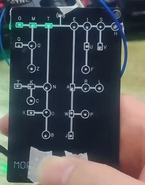
Overview
Morse code is learnt by rhythm: the difference between a short press and a long press is the whole alphabet. That makes it an unusual electronics problem — the value of the device is not in what it displays, but in how quickly and how clearly it answers what you just did.
So the interaction came first. The device reads a press, decides whether it was short or long, and answers in two senses at once: an LED for the eye and a buzzer for the ear. Everything else in the project — the electronics, the board, the assembly — is built around that one loop.
How it works
- You press
A short press and a long press are the two inputs the device works from — the same distinction Morse itself is built on.
- The press is classified
The device decides which of the two it just received, as it happens, rather than after the fact.
- It answers in light
An LED reflects the input, so the learner can see the rhythm they produced.
- It answers in sound
A buzzer gives the same answer audibly — which is the sense Morse is actually used in.
Electronics design
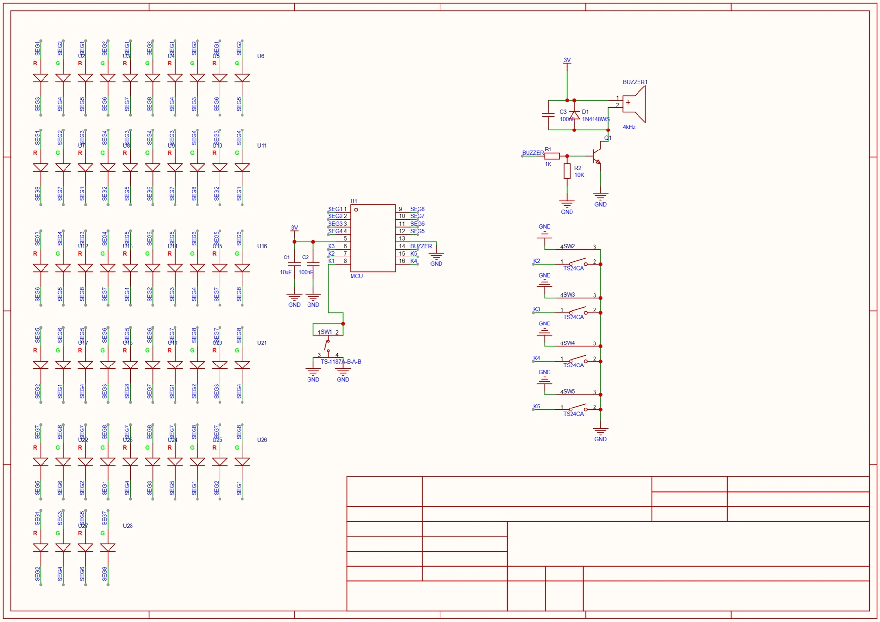
The electronics were designed for this device rather than adapted from an existing board. The schematic captures the input, the LED drive and the buzzer path, and the component list was chosen around the interaction the product is built on.
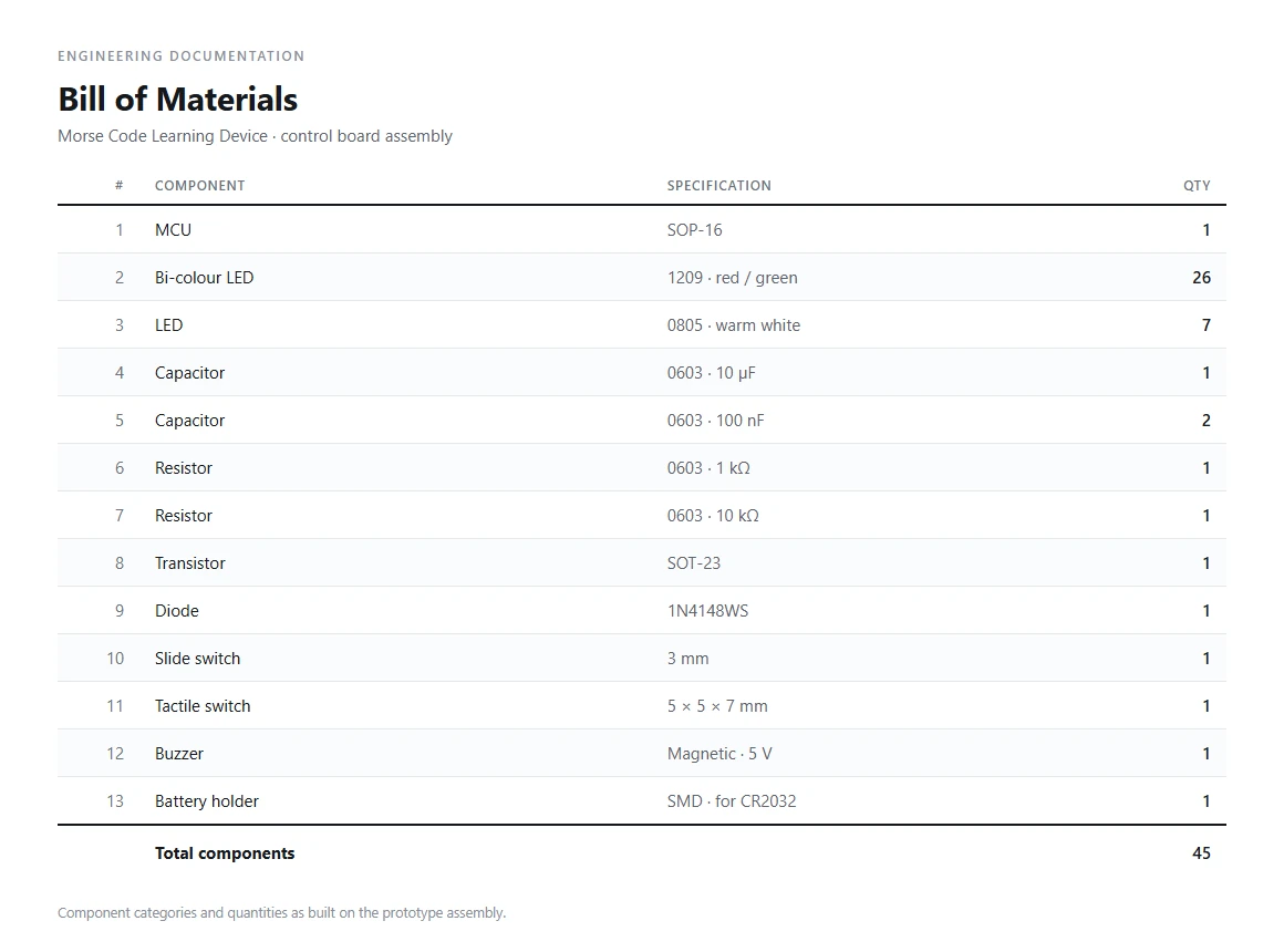
The design runs a small SOP-16 microcontroller, 26 bi-colour red/green LEDs — one for each letter on the front panel — and seven warm-white reverse-mount LEDs. Around them sit the parts that make the board work: decoupling capacitors, a transistor and a diode in the drive paths, a slide switch, a tactile switch, a buzzer and a CR2032 holder.
The schematic shown here is the design reference at V1.0, dated 2026-05-09 — the design as it was drawn at that point, not a final production release. The full schematic is also available as a PDF: Schematic design reference, V1.0 (PDF).
PCB and PCBA development
The board was laid out from the schematic and built up as a prototype sample. Fabrication and assembly run through the manufacturing partner for the project, with our team driving the design, the bring-up and the testing.
The board came back and was brought up on the bench — powered, checked and debugged until it ran on real hardware rather than only in the design file. The video below is that stage.
Enclosure integration
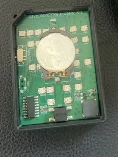
The enclosure is where the electronics and the mechanical side have to agree. The front panel carries the Morse tree, and the light from the board has to reach the right letter through it — so the board layout and the panel are designed against each other rather than one after the other.
The photo below is the assembled board in its enclosure.
Functional testing
The prototype is exercised as a working unit: power on, press, and the device answers — an LED for the input and the buzzer for the rhythm. Short presses and long presses are run in sequence to check that each one is classified correctly and answered immediately, in both light and sound.
The video below is the prototype running, with the Morse tree lighting up in response to input.
Where the project stands
- Interaction design — short-press and long-press input, answered immediately in light and sound.
- Electronics and PCB — the input and the two feedback paths are what the board is built around.
- PCBA — assembled and brought up as a working unit, so the interaction could be tried rather than described.
- Functional prototype — it works as an interaction. It is not a finished product yet.
Related services
Electronics Product Development
How we take a product from a use scenario and its requirements through engineering, PCB, enclosure, assembly and testing.
See how we develop a productPCB Design
Schematic, layout and design-for-manufacturing review, handed off cleanly to assembly.
See PCB designPCBA Manufacturing
Fabrication, components, SMT and through-hole assembly, testing and QC, coordinated end to end.
See PCBA manufacturingBuilding something that has to be learnt by hand?
Send your files — or just a rough idea. We'll review your project and tell you the next step.
No files ready yet? That's fine — start the conversation and we'll tell you what's needed.